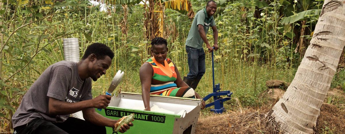
The aim of the project is to develop an affordable micro-scale gravity-fed drip irrigation system for Burro in Ghana. The target customers own small farms or large gardens and primarily grow vegetables. They do not necessarily have previous experience with irrigation technologies but have access to some kind of free or very cheap water source.
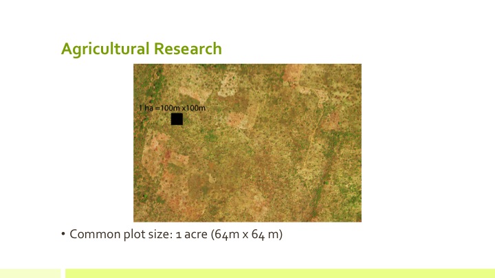
We are currently considering a system size of around 1/16 acres. That way, a 1/8 acre plot can be covered by two systems and a 1/4 one by four. This also allows farmers with more than ⅛ acres of vegetables to try out the system on just a fraction of their land before shifting to drip completely.
The containers should require filling once or twice per day and the drippers should deliver an amount of water appropriate for growing common vegetables like tomatoes in the dry season with no additional water needed. The system should also be able to remain in place during the rainy season so it can be used to counter the threat of crops dying from an unexpected period without rain.
The system should be modular, such that a farmer who already owns their own tank and stand (or has access to a cheap one) can connect the system to it easily, while those who don’t can buy special ones that we design. Similarly, our thought is that some customers might want to buy a treadle pump like the one Burro already sells to fill their containers, while others might have access to pressurized water or a gasoline pump – for example by borrowing from a neighbor for the relatively short daily period it would take to fill the tank.
The cost should be such that the system pays for itself in 3-6 months through extra crops, better quality, savings on fertilizer, savings on labor, increased income security, etc. Setting up irrigation for a ¼ acre farm with the system (through multiple units and possibly extension products) should involve an investment of no more than $200, including purchase of our storage tank but not including a pump for filling it. The design should facilitate easy adaptation of drip irrigation for people who have no prior experience with the technology. It should also be easy to replace broken parts without completely disassembling the entire system.
Our deliverables for Burro will include a working prototype of our system, extensive documentation on our research and design process, and a network of potential partners to work with on refining the product.
-161-169 drippers can be made from one 12” x 24” (⅛” thick) acrylic sheet
2. Cut 300 pieces of 1/16” ID, 1/8″ OD food-grade PVC tubing
-Each piece is ~8” long
3. Attach PVC tubing to dripper and align with indented mark
Pipes
1. Cut 12 pieces of 1” oval piping for the laterals
-Each piece is 49.21’
2. Cut 12 pieces of 2” oval piping for the sub-main line
-Each piece is 4.10’
3. Cut 1 piece of 2” oval piping for the main line
-Piece length is dependent on height of tank
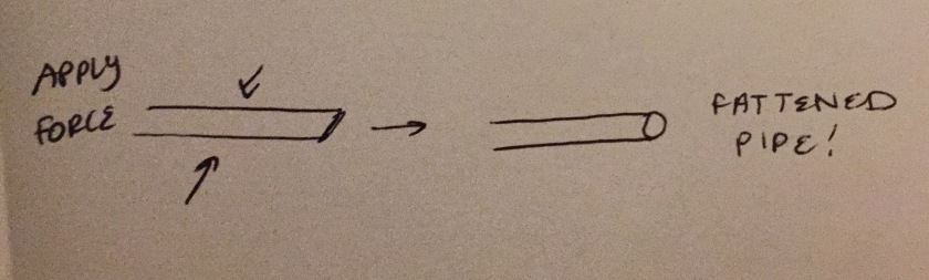
4. Unflatten piping (flat → oval shape)
-By hand / stepping along the creases of the flattened piping
5. Use hole puncher to create opening for drippers every 23.6”
-Add drippers to openings
-Should be a total of 25 drippers evenly spaced along 1 lateral line
6. Use gorilla tape to seal the ends of the laterals
Tank
Design
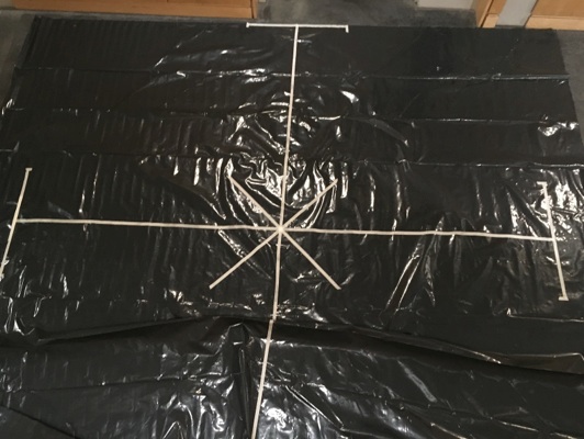
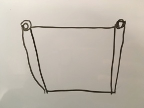
Begin with one square sheet of 6mil polyethylene plastic. Mark A cross___
Fold the plastic in half along one of the long crosses. The wider object of the process is to connect the tips of the bars on the Ts.
Tape town the edge across the diameter marks. Fold the sides up as shown so that the full top of the T shows. Do this on both sides.
Tape down the edge.
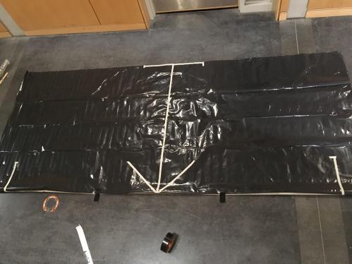
Flip over and fold the edge over along the stem of the T. See Below.
This is what it should look like folded. Tape down this side too.
It should now look like this, with both Ts folded along their stems and taped on both sides.
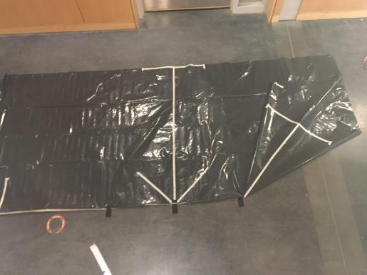
Now, pull out the sides, and fold flat so what was on the edge is now in the middle. That T in the middle is what was just folded over and taped in the previous steps.
Connect the ends of the Ts in the previous picture and tape them down so they’re touching, as in the photo above.
Turn it over and do the same on the other side.
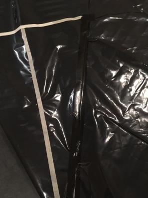
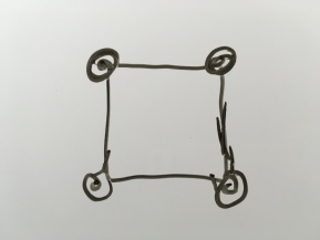
The tank should now look like this. There should be a tape ring all the way around the top like above.
Place tape rings around the tank every six inches down the sides of the tank. The first ring can be seen above (black ring near white tape ring).
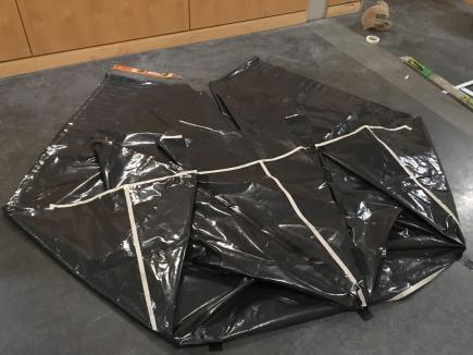
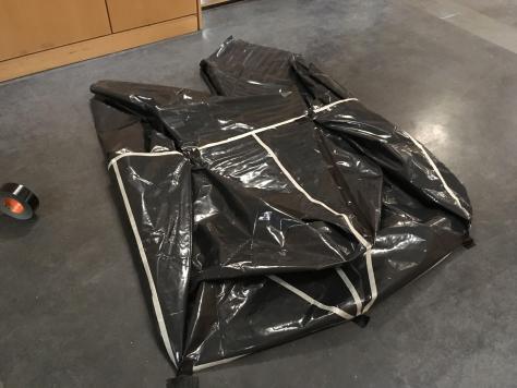
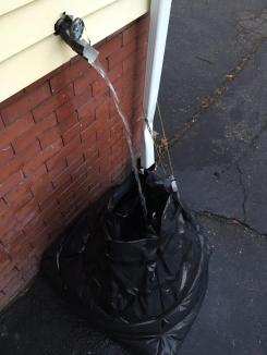
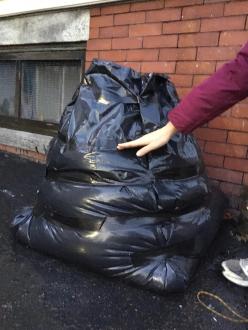
The completed tank. Once the black rings are on, the tank can be pulled upright and opened up. Fold the edges over like above and tape them down. If the edges are not taped down, they will sink into the tank and the tank will not hold water. Keeping the edges out of the tank is very important. Add rods as shown above to help stabilize tank when empty. When full, the tank should hold itself up.
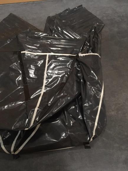
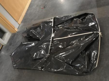
For easy transport the tank can be rolled up and bound as shown. The rods can also be removed to allow the tank to fold even smaller.
Connections to Filter & Pipe
The filter needs to be attached slightly above the bottom of the tank in order to avoid sucking in settled debris from the tank floor. The filter is made to be attached to a rigid tank like a large trash can using a bulkhead connector. An instruction on how to install the connector can be found here:
A small ring and gasket on each side of the tank wall makes sure the connector can be screwed tightly in place in the hole drilled for the purpose. The pressure at this point is already quite high, so it is important to strengthen the tank around the area. Our solution for that was to just put four layers of duct tape on each side to form a reinforced circle. We then cut out a hole to fit the connector. Testing showed that this resulted in a tight seal.
The filter has a ¼ inch connector on the outlet side, so to connect to the 2 inch mainline, we needed a specialized connector. Our solution was to seal off one of the three sides in a 2” to 1” tee-connector and then attaching it to the connector with a small piece of hose that happened to fit. More elegant solutions are certainly achievable, but in testing we saw that our method held tight.
Putting the System Together
1. Elevate Tank
2. Connections
-Use modified 2” to 1” tee-connector to connect filter end to mainline
-Use 2” to 2” tee-connector to connect the mainline to the sub-main line
-Apply metal fasteners as a reinforcement to prevent leaking
-Use 2” to 1” tee-connectors to connect the sub-main line to the laterals
-Use elbow connectors for the ends of the sub-main line
3. Straighten out any lines that are bent.
4. Fill the tank with water!
5. Check performance of drippers. Adjust rates as needed.
The role of the storage tank for the system is twofold. First, the surface of the water must be high enough to achieve sufficient head height to propel water through the system. Second, the tank must securely store all of the water required for the system to run for half a day between fillings. It must perform these roles over years of use in a harsh climate under constant load, without being so expensive to manufacture, ship or maintain that it makes the system unaffordable to Ghanaian farmers. Designing such a tank was a challenge, but the end result satisfies the needs of the project well.
Design Considerations
Before design of the tank began, a list of considerations and challenges was made to guide development. The main challenges for the design were shipping costs, volume considerations, and usability.
Shipping Costs
Shipping ability was possibly the most important factor for tank design. Manufacturing the tanks will have to be done in China, since Ghana lacks the industrial resources to make them locally. Although this means that manufacturing the tanks will be relatively cheap, it makes shipping much more of a concern. Empty water tanks are very expensive to ship from China, since they take up a lot of container space each. Once they arrived in Ghana they would still be prohibitively expensive to move. Ghana lacks a formal mail system. Most parcels are either hand delivered or shipped on the public buses. Shipping a large bulky object across the country in that environment is nearly impossible. To minimize shipping costs, the team decided to pursue a folding, bag type tank design. A flexible structure is ideal because it can be shipped as a compressed bundle and unfolded to full size on site. This eliminated the problem of having to ship a large, bulky item long distances.
Volume Considerations
To feed a system of 1/16 of an acre containing 250 drippers, a tank of 200 gallons is required, assuming twice daily refilling. This presented a challenge, since 200 gallons of water weighs 1670lbs. This meant that the tank had to be designed in such a way to cope with that amount of weight, without being so large and heavy when empty that it could not practically be shipped to and around Ghana. The most likely place for a flexible tank to fail is at the seams. If the structure is made from multiple pieces or is cut to shape and assembled, it will have inherent weak points where pieces of material were joined. To guard against this problem, a folded, origami style design was employed. This created a tank that was completely seamless and thus had no inherent weak points.
Usability
Usability was a big factor in tank design. Drip irrigation is a new concept to many Ghanaian farmers. A difficult or inefficient first experience could very easily turn them off it. Water tanks at their best are large unwieldy objects requiring daily work to fill and clean them. If they were hard to set up, did not stay upright, collapsed and spilled, or were hard to clean or fill, people would just abandon the system. So it was imperative that the tank deliver a satisfactory experience to users. To make the user experience as simple as possible, the tank was designed to stand on its own when full, using the hydrostatic pressure of the water inside to hold the sides open (see Research and Calculations Section for details). A self-supporting tank means that the user will not have to build a support system for the tank or set it up by a supporting structure like a tree.
Materials
With these design considerations in mind, the next step was to choose materials for the tank. The two factors most influencing the choice of materials were pricing and durability.
Pricing
The price of the material was very important to the success of the system. Most Ghanaian farmers will only buy a product like this if it costs less than $100. A 200-gallon water tank could easily cost much more than that all by itself. Keeping the price low enough to be accessible to the target market was a challenge. This factor limited material options to plastics, as they can be cheaply manufactured in large quantities.
Durability
Durability was another big factor. Plastics will not biodegrade or rust, but some will degrade in sunlight or with extremes of temperature. A water tank holding 200 gallons outdoors on the equator is under a lot of sustained stress both in terms of water pressure and holding up against the climate. A material that could cope with these stresses over a long period of time was essential. For this reason, Polyethylene was chosen as a material. It is a strong, flexible plastic that does not degrade in sunlight or heat. Vinyl, and its derivative PVC, are sometimes used in similar applications such as inflatable boats and heavy tarps. For this reason, they were initially considered. However, they were ultimately rejected due to the fact that they degrade in sunlight.
A Local Sourcing Exception
There was one material that could be locally sourced in Ghana, bamboo. Easily accessible and cheap, it allowed the possibility of a rigid tank or at least tank support structure that was locally produced. Bamboo has a very prominent grain and is very flexible and strong in the longitudinal direction. Therefore, supporting a large storage container seemed to be a good use for this cheap and plentiful material. However, there were concerns over whether bamboo would be able to withstand repeated exposure to water. As with most plant-based materials, bamboo would rot over time if frequently exposed to water. Additionally, bamboo has sharp points where branches have been broken. This could puncture a bag inside the bamboo support structure. Finally, bamboo left in sunlight will crack over time, creating more sharp edges and compromising the material’s structural integrity. Ultimately, despite its accessibility and attractive price, bamboo was dropped as a material choice due to these issues. It was however, retained in a minor role in the final design, as thin, disposable support rods that can be used to prop up an empty tank to make it easier to fill. Use of bamboo in this context was deemed acceptable because the rods are solely a convenience and not necessary for the function of the tank, the load was not very large, and the rods could be easily removed and cheapy replaced it they broke or started to rot.
Calculations and Models
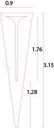
Designing a tank that could support itself with its own internal water pressure required computer modeling. The tank was designed as a truncated cone to maximize both stability and head height.
To maximize head height, the optimum tank shape would be a tall narrow cylinder. A tall narrow cylinder brings the water height as high as possible. However, a flexible column of periodically turbulent liquid with a small footprint can easily nudge its center of gravity out of its footprint and topple. Any irregularities in the shape of the walls will magnify this risk. Additionally, a thin cylinder will drop water level very quickly as the tank is drained, leading to highly variable pressures between a full tank and an emptying one.
A wide low cylinder solves both these problems, because the large footprint is much harder to tip, and a large water surface falls more slowly as water drains. But it creates a tank with an impractically large space need, large losses to evaporation, and a very low head height. Since the pressure in the drip system comes from the height of the water level in the tank, the tank needed to be as tall as possible while still being stable.
A truncated cone with slightly angled walls was the best option. It has a wide base to increase stability, but a continually narrowing profile to maximize head height. However, angling the walls presented the potential danger of having the walls fall into the tank with gravity. Hydrostatic pressure, the only force keeping the walls under tension, acts perpendicular to a surface. It acts at the middle of a wall and its magnitude is a function of the height of the surface of the water:
Where ρ is the fluid density, g is the acceleration due to gravity, and h is the depth of the point being measured compared to the fluid’s surface. As the water level increases, the hydrostatic pressure on the side walls increases, but so does the weight of the walls themselves. If the side angle of the cone was too large, the walls would collapse under their own weight. The correct wall angle was needed to ensure adequate head height without risking cave in. This optimum angle was calculated using the software ABAQUS.
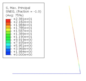
The following figure shows the Abaqus simulation of a cross-section of the tank. In a real-life model of the tank, this portion of the bottom of the tank and the side of the tank would be rotated about the center axis. This graph shows the Von Mises Stress across the tank surface. Von Mises stresses show an estimated measure of the point in a material which is most likely to yield first, especially for plastically deformable materials. As shown by this simulation, the tank is most likely to yield at the center of the slanted surface, where the hydrostatic pressure is maximum. Also, the tank is likely to fail at the bottom corner of the tank, where a drastic turn causes a geometric irregularity and, as a consequence, high concentrations of stress. In the final tank design, this angle was rounded to reduce this stress.
ABAQUS model stresses
To make a storage tank of appropriate scale, the volume of the tank was held at a constant value of 200 gallons. Then, the radius of the bottom of the tank was set at a constant value that could create a tank of that volume. Wall angles between 60 and 80 degrees were tested for sufficient hydrostatic pressure. The formula for the volume of a truncated cone, along with trigonometric identities, were used to find the relation among the volume of the truncated cone, the radius of the base, and the angle of the slanted sides of the tank with respect to the bottom of the tank.
70 degrees was determined to be the optimum angle for the tank walls. The angle of the sides of the tank also determines the slant height of the tank and, thus, the amount of material used. 70 degrees was also the angle at which the most volume could be enclosed with the least material, making it the most material efficient choice as well
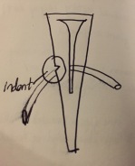
Initial Designs
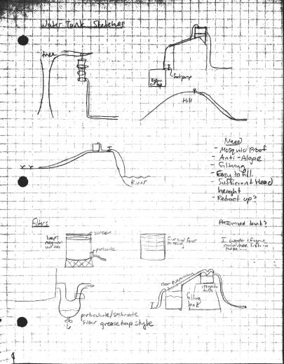
Initial designs for the tank were quite diverse. Many sketches and ideas went into creating a product to fit the needs of the expected user base. These included long narrow bags hung from trees to maximize pressure head height, rigid plastic or bamboo structures, and flexible bags with wooden support structures around them. As research and calculations progressed however, the design was narrowed down to the flexible polyethylene truncated cone discussed above.
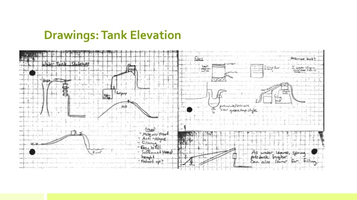
Initial Design Sketches
First Iteration
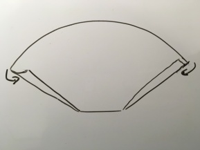
Creating a watertight tank capable of holding 200 gallons of water out 6mil polyethylene sheeting was definitely a challenge. The most successful early design was made by folding a square sheet of the plastic into a cone shape. The walls were taken at four corners and curled until the sides had risen up into a cup shape. (See diagram). A small (10 gallon) prototype of this design showed great promise, but had a few problems. Although it was completely watertight, because the curled corners were only secured at the top, the water pressure pushed out of the sides curls in the bottom half of the tank and turned the cone into a pancake. A masking tape retaining ring placed near the top kept the water from pushing out the walls past it. This indicated that the tank needed retaining rings in order to keep its shape.
Initial Design featured curled sides.First Iteration Design with sides curled up to form cup shape.First Iteration Design Top View Sketch. Note curled corners.
Second Iteration
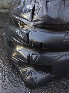
The second iteration of the design had retaining rings of heavy duty Gorilla brand tape placed every six inches along the walls. The tape was used because it was cheap, easily accessible, and very strong, both in adhesive quality and in the strength of the fabric. This ensured that the rings would withstand the water pressure, and not slide up the cone as the pressure below pushed them. It also had pleated walls, instead of curls. Pleats were chosen because of their neater profile and more consistent behavior under load. This test was highly successful, easily holding 100 gallons of water and keeping the desired 70-degree cone shape. The only issue it ran into was caused by human error. Rods placed in the tank to help it stand while empty were left in the tank while it filled. The rods were secured to the tank rim, and as the tank filled and bulged out, the rods were driven into the floor, puncturing it. The holes were actually less of a problem than would be expected, because the weight of the water in the tank prevented much from escaping through them. The extent of the damage was only discovered after the test. The rods were not supposed to be placed in the tank at all. Rods secured to the outside of the tank were considered but the inside ones were just for aesthetic purposes before the test.
Filling the Iteration 2 prototypeThe importance of the retaining rings was readily apparent during testing.The maximum water level in Iteration 2 (hand level) was significantly lower than the rim of the tank due to the height of the pleat edges.
Final Design
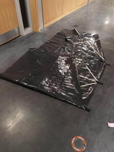
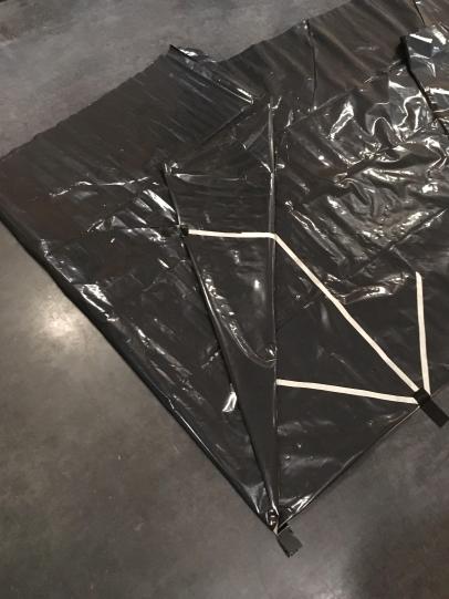
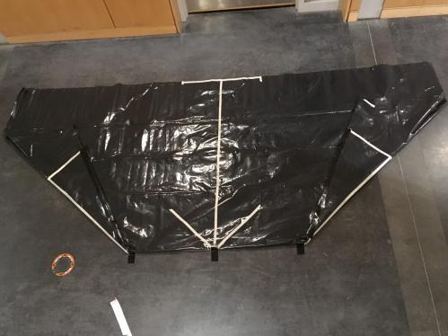
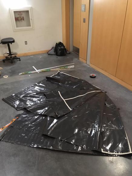
The final iteration of the design had all the elements of the second iteration, but was full size. This presented challenges of its own. The tank’s larger structure meant it was heavier, and had more pleat plastic to control. It was not as stiff as the second iteration when empty, since the walls were the same width but had to carry more weight. For this reason, external support rods made from bamboo were placed along the corners, each in a sleeve made from Gorilla Tape. The tops of the pleats also presented a challenge, as they were very bulky and hard to control. They were trimmed to a more manageable size and secured to the outside of the tank to keep them from sinking down into the tank during filling. The pleats were also much more organized and tightly controlled in this iteration than the last, with more folds per pleat and more secure adherence to the walls. This measure was structurally important as well as aesthetically pleasing. The tank’s maximum water level is limited by the height of the top edge of the lowest pleat. If the pleats were not secured at all, they would sink into the middle of the tank and let out all the water. If they were only tacked to the walls in the middle of their edge length, the two smaller pleats created would sink as far as they could. To maximize the potential height of the water level in the tank, the pleats were folded several times and secured tightly to the wall with the edges folding over the rim. This combined with the retaining rings ensured the tank kept its shape and held water. The last difference between the final iteration and the previous one was a guard layer of plastic placed across the bottom of the tank. Because of the pressure on the bottom of the tank, thicker material is needed there to protect against sharp objects under the tank, especially if someone might try to move the tank, dragging it across the ground.
Origami Tank Folding Steps.
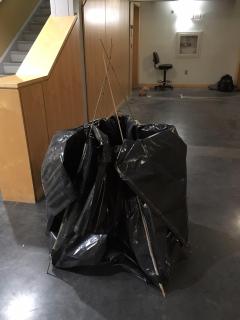
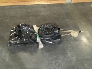
Final Design Prototype standing empty with removable support rods.Final Design prototype rolled up for transport. It rolls to roughly a third that size with the support rods removed.
Conclusion
The tank design that came out of this process does everything it needs to do. It is lightweight, folds for easy shipping, is cheap to produce and is made from durable materials that can stand up to years of use outdoors. It is very different than any other water storage tank on the market, but that is because it was designed to handle conditions most water tanks could not. The environment in Ghana, both climate wise and economic, requires a specially designed tank, and that is what was designed.
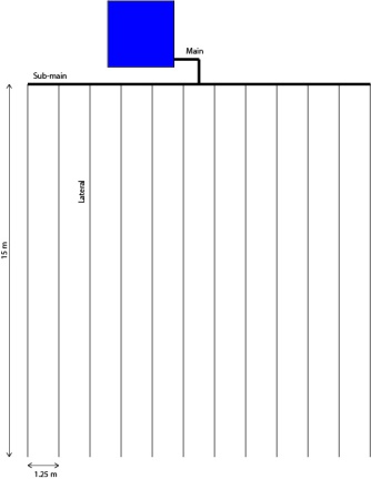
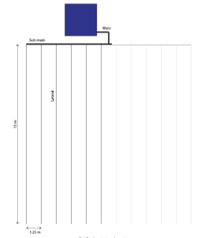
The mainline length was assumed to be 13.12 feet, while the laterals are 49.21 feet with a spacing of 4.10 feet (dimensions were initially given in meters, but have been converted to feet for unit consistency). The junctions between the sub-main and laterals are tees, while the bend in the mainline and the junction between the sub-main and the outermost laterals are short elbows. There is also a fully-open ball valve along the mainline.
The figure below shows a schematic of a 1/16 acre system .
Diagram of our piping
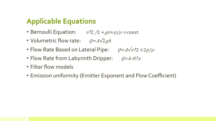
The pressure model assumes that water moves through the system at a consistent flow rate regardless of the pipe diameter, which can be achieved if the tank is high enough and the drippers are properly adjusted. The flow rate through each dripper is 0.5 gallons/hour, so the flow rate at the beginning of each lateral is 12.5 gallons/hour. The flow rate through each segment of the sub-main is the sum of the flow rates through the laterals that obtain their water through that segment. The flow rate through the mainline is twelve times the lateral flow rate (150 gallons/minute). The velocity through each section is the flow rate divided by the pipe cross-sectional area .
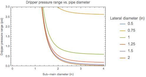
The pressure drop through a section of smooth pipe is , where f is a friction factor that depends on the pipe roughness and the Reynolds number of the flow but can be approximated as 0.02, l is the pipe length, ρ is the water density (1.94 slugs/ft3), V is the water velocity, and D is the pipe diameter. The pressure drop through the other obstacles (tees, bends, and valves) is , where K is a constant depending on the geometry of the obstacle (0.05 for the open valve, 0.3 for the elbow, 0.2 for flow along the linear part of the tees, and 1 for flow between the branched and linear parts of the tees).
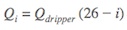
Since the drippers are evenly spaced along the laterals, the laterals do not have a consistent velocity along their length and thus do not have an even pressure drop. Since there are 25 drippers, each releasing the same amount, the flow rate right before the ith dripper is . The velocity through each segment is , and the pressure drop through the segment just before the ith dripper is . The total pressure drop through the laterals is .
The total pressure drop through the piping, not accounting for the pressure drop through the drippers, is the sum of the pressure drop through the valve, the first elbow, the mainline, the branched part of the tee connecting the mainline and sub-main, the 5.5 segments of the submain, the five linear parts of tees, the elbow at the end of the sub-main, and the lateral. These equations were entered into Mathematica and combined to an equation finding pressure drop depending on the diameter of each pipe type.
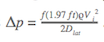
The following plot shows the pressure change from the tank to the dripper that is farthest from the tank as a function of the pipe diameter. For this, the mainline and sub-main are assumed to be the same diameter. The pressure at the bottom of a 10-foot column of water is 4.33 psi (marked by the gray dashed line), so the total pressure drop must be lower than this. It is apparent that the mainline and sub-main must be at least 2 inches in diameter, and that the laterals must be at least 1 inch in diameter to keep the pressure drop low enough. The pressure drop would be limited with increased pipe diameters, but the benefit of mainline and sub-main diameters over 2.5 inches and lateral diameters over 1 inch would be somewhat limited.
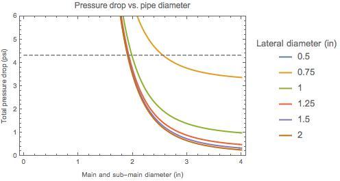
Another key metric for the effectiveness of the system is the range of pressures occurring at the drippers. Since the water must flow through different lengths of piping to reach different drippers, not all drippers receive water at the same pressure. The following plot shows the difference between the pressure at the dripper closest to the tank and the pressure at the dripper farthest from the tank. To achieve a reasonable pressure range, the sub-main diameter needs to be at least 2 inches, and the lateral diameter needs to be at least 1 inch. The mainline diameter has no effect on the pressure range, since all water must flow through the entirety of its length.
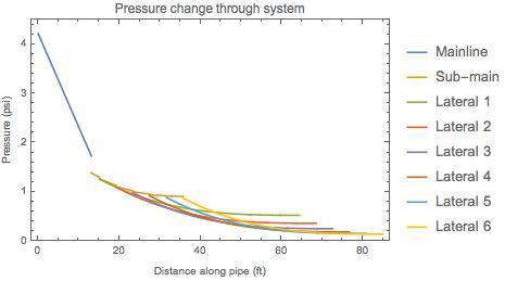
The ideal pipe diameter appears to be 1 inch for the laterals and 2.5 inches for the mainline and sub-main. However, due to the limited availability and cost of fittings for pipes with a diameter larger than 2 inches, the most reasonable diameter of these pipes is 2 inches. For a system with these diameters (1 inch/2 inches), the total pressure drop to the end of the furthest lateral is estimated to be 4.19 psi and the pressure range is 0.95 psi. Thus, the tank would need to be elevated to at least 10 feet, although a higher tank would allow more control as the water level drops. The change in pressure throughout the system with a tank height of 10 feet in the following plot. For the purpose of clearly demonstrating where the most pressure is lost, this plot assumes that the water enters the mainline at full pressure, while in reality most of the pressure increase due to gravity occurs in the main line. The laterals are numbered in order of distance from the tank, with Lateral 1 being closest and Lateral 6 being farthest. Since the system is symmetric, only half of the laterals are shown. Most of the pressure drop occurs in the mainline, so any attempt to increase the pressure at the drippers should focus on either shortening the mainline or increasing its diameter.
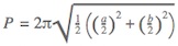
The previous analysis assumes that all piping is circular. If the piping is oval, there will need to be an adjustment for the equivalent diameter (the diameter of circular pipe with the same impact on pressure change). The equivalent diameter for elliptical pipe given its area and perimeter is . The area given major diameter a and minor diameter b is , and the perimeter is . The following plot shows the pressure drop through a 30-foot pipe with a constant flow rate equivalent to the flow rate at the beginning of the laterals and a perimeter of 3.14 inches (equivalent to a circle with a 1-inch diameter), as a function of the ratio between the minor and major diameters. As the pipe becomes more oval (b/a approaches 0), the pressure drop increases, while the pressure drop decreases as the pipe becomes more circular (b/a approaches 1). This would imply that circular piping is superior to oval piping for limiting pressure drop. However, the difference is small as long as the minor diameter is at least 80% of the major diameter, so oval piping is suitable as long as it can be formed to a reasonably circular shape.
Pipes and Joints
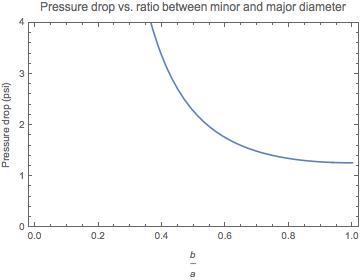
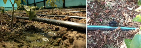
When choosing materials and sizes for the piping for the main-line, sub-main and laterals the main design constraints were ease of transport and meeting the requirements for pressure and losses which are outlined in the previous section. The final design used oval piping. The material choice was agriculture and food safe polyethylene plastic. The oval piping are flattened during transport and, with minimal work and the aid of water flow, can be easily returned to their circular shape.
The lateral piping is easy flattened for shipping and transport purposes. 15 meters length 1″ diameter oval piping.
Though flexible, the oval piping had enough rigidity that the dripper hole puncher and drippers could be used. Although oval piping was used in the final prototype design, layflat piping is another valid option. If layflat piping was used the method for inserting the drippers and for keeping the micro-tubing attached to the piping would need to be investigated further. In the case of a leak, for example due to a misplaced dripper hole or a crack or break in the pipe, the best solution was to apply duct tape to the surface once it was dried.
As mentioned in the previous section the laterals were 1” diameter in order to reduce the bulk of piping needed while the mainline and sub-main line were 2” diameter to limit the pressure losses in this line. To connect the pipes, Tee-connectors were used to connect the mainline to the sub-main, 2” to 2”, and the sub-main to the laterals, 2” to 1”. Elbow connectors were used for the ends of the sub-main. The 2” connectors needed metal fasteners as a reinforcement to prevent leaking.
Having clean water is essential to the function of a drip irrigation system. If the water supply contains particulate, it will clog the hose lines and the emitters. However, in many areas, clean water is just not available. For this reason, it is necessary to include a filtration system in a drip irrigation system in order to ensure its continuing function.
There are two basic types of irrigations filters:
Pre-filters – Filters that the water passes through before it enters the storage tank.
Post-filters – Filters that the water passes through after leaving the storage tank on its way to the irrigation piping.
PRE-FILTERS
Background
Pre-filters are filters that come before the storage tank in the path of water from the source to the fields. They have an advantage over a post filter in that the pressure loss they cause does not affect the pressure of the rest of the system. They are also easier to access for cleaning, repair and replacement. However, they cannot affect particulate that gets into the water supply downstream from them. For example, dust entering the tank will not be filtered out by a pre-filter. The most practical places to put a pre-filter are on the end of the filling hose, or over the entrance to the storage tank. For this experiment, we focused on filters that were put over the end of the filling pipe. In this experiment, we tested a number of potential pre-filter materials. Materials were tested for effectiveness at clearing particulate, speed at which water flowed through them, and accessibility and cost.
Equipment & Procedure
This part of the experiment focuses on material testing. We mixed dirt (~18 oz) and water (about the amount of a small bucket) to make dirty water and tested the effectiveness of the different filters by running this water through them.
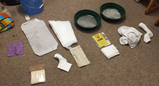
Top Row (L to R): glasses cloth, fine straining bag, mesh, regular metal filter, fine metal filter
Bottom Row (L to R): cheesecloth, sock, burlap bag, small fine straining bag, t-shirt, sock with leaves
We selected 11 different materials to test: t-shirt (cotton), glasses cloth (microfiber), cheesecloth, sock (polyester), sock with leaves, burlap sack, fine straining bag (plastic), small fine straining bag (plastic), mesh (plastic), regular metal filter, and fine metal filter. Additionally, we tested the effectiveness of charcoal in conjunction with the existing material.
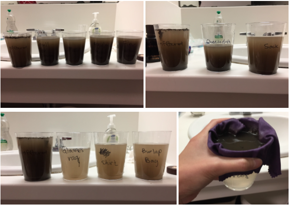
To collect the water, we used clear plastic cups to collect the water passing through each material. Each filter was placed on top of the plastic cup, and ~9 oz of dirty water was passed through the filter. The next section highlights the results from our testing.
Data
We used a rating scale to assess the quality of the water sample for each material. (1) being very clean and (10) being extremely dirty. The control sample (the unfiltered water) was set at (10), and all other samples were compared to this one. We also took note of the time (slow, fast) that it took the sample to pass through the filter.
Filtered Samples
Discussion
From our results, we found that the filter materials with significant results were: glasses rag, t-shirt, and burlap bag (ratings of 0.5, 2, and 3, respectively). Of these, the burlap bag was the fastest in filtering the material, and the glasses rag was the slowest. The other materials did not produce significant results (all with a rating of 6 and higher).
In the charcoal test, we found that it was difficult to distinguish between what was dirt from the water and what was particles from the charcoal. The filtered sample ended up being the same or even worse in dirtiness than the control sample. Furthermore, charcoal is supposed to help with removing metals, but not so much large particulates. We realized that perhaps this was not the most effective method to check the efficacy of charcoal, but for our purpose of large particulate filtering, we ruled out charcoal as a material for pre-filtering.
We also observed that material passes much quicker through a bowl or bag-shape than through a flat sheet. That is, when we stretched out the material on top of the cup, the water passed through more slowly. When we let it concave a bit, the material passed through faster.
Conclusion
Our results showed clearly which materials were best suited for use. The T-shirt, burlap bag and glasses cleaning microfiber cloth were the most effective at filtering particulate. However, due to its higher cost, the microfiber cloth is unlikely to be practical. Similarly, the T-shirt was effective, but water ran through it very slowly. This leaves the burlap/drop cloth material. This material was the clear winner, with a low cost, high water flow rate, and high percentage of particulate removal.
POST-FILTERS
Background
Post filters are filters that sit between the storage tank and the irrigation piping. Post filters are important because they are a direct barrier to any particulate entering the piping system that might clog the drippers. Even if particulate gets past a pre-filter, a post filter will stop it from reaching the drippers. The one big drawback faced by a post-filter is the fact that the drop in water pressure across it directly affects the drippers downstream. A filter with a high resistance will require a tank with a higher pressure head, which means higher elevation. There is a commercially available post filter that is designed specifically for gravity-powered drip irrigation system and is relatively cheap to purchase. However, the data for the pressure lost it creates was unknown. So we ran some tests to see how the filter affected the pressure in the pipes at different flow rates.
Equipment & Procedure
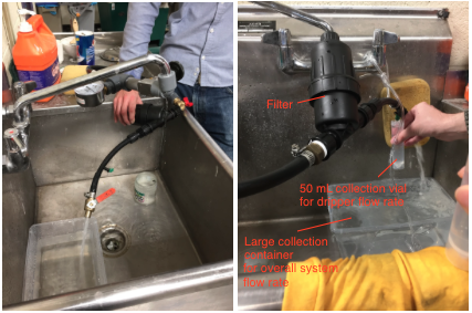
To test the pressure drop across the filter we made a test rig. The test rig consisted of a pipe, with a faucet at one end, a valve on the other, the filter in the middle, and drippers on either side of the filter to test pressure loss. The drippers are very sensitive to pressure drops in the piping. Pressure loss could be calculated from the difference in drip rate on either side of the filter, using data collected earlier on the relationship between pressure and drip flow. We used a pair of valves at either end of the rig to modulate pressure and flow rate to simulate a full irrigation system. We used this rig to measure pressure loss across the filter at a range of flow rates and inlet pressures.
Post-Filter Testing Set-Up
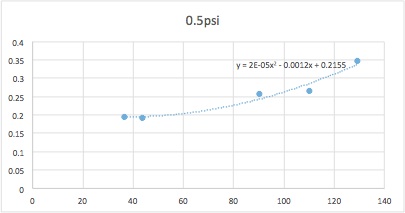
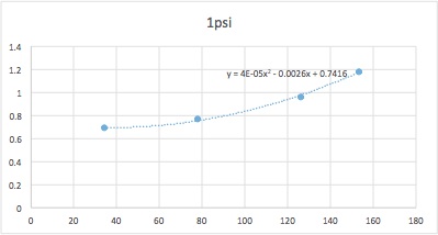
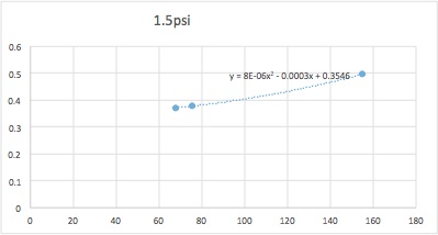
Data
The graphs for the three trials of 0.5psi, 1.0psi, and 1.5psi is shown in the figures below. For each trial, the flowrate of the system was set at values ranging from 30GPH to 150GPH in intervals of 30GPH. Some of these data points were outliers and, thus, were excluded from the final graphs of the data. The first trial at 0.5psi and the second trial at 1.0psi followed a similar trendline and, thus, can be modeled mathematically. However, the third trial at a system pressure of 1.5psi had data which did not follow the trend of the other trials. The final graphical models of the filtration testing, for system pressures of 0.5psi and 1.0psi, are shown below.
Discussion
The goal of these tests was to ensure that the post-filter would not cause an unacceptable pressure drop when used in a low-height gravity-powered drip system. This is why the system was tested at such low inlet pressures. The planned system is expected to work at around 2 psi, slightly above the test pressures. This means that if the filter doesn’t reduce the pressure to an unacceptable level at these inlet pressures, it should work under the expected pressures in the system.
Though we cannot determine at this time whether or not the pressure drop measured is acceptable, the information will be vital for determining the viability of the system later, when more variables are known.
Significantly, in all trials, the pressure loss caused by the filter becomes insensitive to flow rate at low flow rates. This indicates that even if the irrigation system behind the filter is small and does not contain many drippers, the filter will not block its use.
Outliers in the data were left out because they were likely caused by faults in the rig used, such as imperfect fittings between the sections of pipe leaking. This is also probably the reason the 1.5 psi data did not fit the trend of the other two. At the higher pressure, the system was more prone to leakage.
Conclusion
The data collected in these tests will be used in conjunction with the results of tests of other parts of the system, allowing us to design a system of components that work well together. Due to the limited ability of our test rig, the data for the 1.5 psi trial will be left out. However, this is acceptable because we were more concerned with the filter’s performance at low pressures rather than high pressures.
During our initial research, we quickly realized that drippers would be a key aspect of the design. There are multiple challenges related to designing good drippers for gravity-fed systems, some of which are:
Drip rate stability: the pressure in gravity fed systems falls as the water levels in the tank gets lower, so it is important that the dripper can to some extent compensate for this and keep drip rates fairly stable.
Price: a lot of drippers are needed, so even cheap ones can become a huge expense in the overall system.
Clogging: drippers have a tendency to clog due to small particles accumulating in them, especially when operating at low pressures.
Replaceability: when drippers fail, they need to be replaceable without taking the entire system apart. This is especially complicated with pre-installed drippers.
BACKGROUND ON DRIPPERS
The two main methods for dripping are:
Internal drippers, where drippers are pre-installed and fixed – usually inside a thin tube of a diameter around ¼“
External drippers, which are stuck into holes, manually punched in a larger tube – usually of a diameter around ½”
Left: Internal dripper. Right: External dripper.
We quickly ruled out drip tape through preliminary testing and research. Drip tape is rarely used for gravity-fed systems because inherent issues with clogging are greatly amplified as water pressure decreases and suspended solids increase. When one dripper clogs, no repair is possible and the entire length of drip tape needs to be replaced.
Many different types of external drippers are available through drip equipment suppliers. Most use systems of thin internal canals to slow down the drip rate and compensate for changes in pressures. Some are specifically “pressure compensating”, meaning that they have a little diaphragm that gradually restricts flow as pressure increases to keep the drip rate consistent across larger fluctuations in pressure. Most drippers have fixed flow rates of between 0.5 and 2 GPH, though variable flow rate drippers are also available and are commonly used in gravity-fed systems. We decided to buy a collection of drippers and build a test-rig for them. Most drippers are designed to work best at pressures of 10-40 PSI, which is about ten times that in a typical gravity-fed system. Therefore, we expected their performance to vary greatly across types and brands in our testing.
INITIAL TESTING OF COMMERCIALLY AVAILABLE DRIPPERS
We initially bought a large collection of the different commercially available external drippers and designed a testing rig to see how they performed under the kinds of pressures we expected our system to have. In general, bulk quantities of decent quality drippers range from $0.2 to $0.5 per dripper – our 1/16 acre system would require around 300 drippers at $60-$150 total.
The external drippers are commonly sold for use in drip-irrigation systems that use running water such as a faucet or garden hose, which can generate pressures around 40 psi. The recommended and tested pressures for these drippers are between 10-40 psi. Since our system uses gravity the pressure is generated by the height of the water in the tank. Therefore, in order to maintain a reasonable tank height, our system will likely operate on significantly lower pressures, between 0.5 – 2 psi. Because of this we decided to run experiments to determine the flow rate for a system operating at lower pressures between 0.5 – 5 psi.
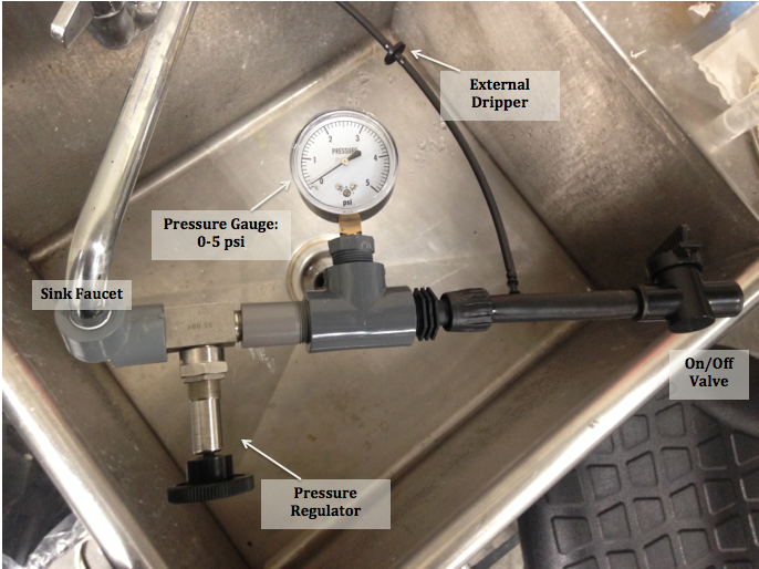
Test Equipment: The pressure regulator and gauge (0-5 psi) is connected to a short length of tubing with an external dripper attached.
We first created test equipment that could accurately measure the two variables: pressure and flow rate. The water pressure from the faucet is regulated at pressures between 0-5 psi. We tested pressures in 0.5 psi increments up 3 psi and then in 1 psi increments up to 5 psi. The water then runs through the tubing to the external dripper and a 50 mL graduated cylinder was used to catch the water. A timer was stopped once the 50 mL cylinder was filled to calculate the flow rate.
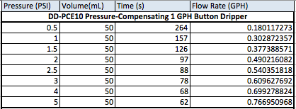
Example of data collection of volume (mL) and time (s) to determine flow rate (Gallons per hour).
After many hours of watching water droplets fall we collected the following data on 22 drippers: Dripper Flow Rate vs. Pressure.
Our results indicated that many of the commercially available drippers were not suitable for our system because at such low pressures they could not produce the flow rates needed. Also as the pressure changed even small increments of 0.5 psi the flow rate changed drastically which is not desirable as there may be small pressures loses throughout the pipe. Though the pressure compensating drippers showed more promise, they were also the most costly.
TUBING AND REGULATOR SYSTEM
We decided to work on designing our own dripper, using small lengths of thin vinyl tubing with a regulator that squeezed the tube to control flow rate. Even the highest quality polyethylene tubes (such as the ones used in food production and medical applications) cost only a few cents per foot. Similarly, we realized that if we designed regulators that could be stamped out of a sheet of plastic, we could make them at a fraction of the price of commercially available adjustable flow drippers (which are injection molded in multiple pieces and materials before assembly) with very little tooling required. During the design phase, our test models could be either 3D printed of laser cut.
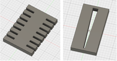
We made two initial designs: one “digital” where the tubing was wrapped around the regulator and fitted into a series of sized slots on either side to squeeze it gradually; and one “analog” where the tubing was fitted through a slit that got gradually thinner, such that sliding it up and down would change the restriction and thus the flow rate.
This system also turned out to offer multiple other advantages. Clogged drippers can easily be flushed out by removing the restrictor temporarily. In addition, broken drippers can often be repaired by just changing out the tubing and keeping the old dripper. Individual drippers can also be turned off by restricting the tubing completely. Finally, the adjusters can be used as weights to place the end of the dripper right at the root of the plant, which optimizes water delivery. We tested the flow characteristics of these with some 5/32” outer diameter 3/32” inner diameter polyethylene tubing.
To test this system we used the same test equipment and procedure as previously.
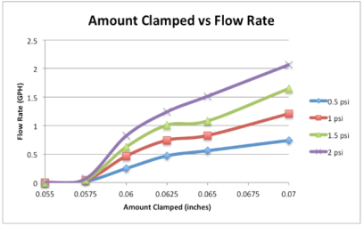
In the digital restrictor we wanted to optimize both the slot width and the amount of wraps. Before 3D printing the design we did preliminary testing of the slot width by clamping multiple calipers at the same measurement. Using these data we decided to test a slot spacing of 0.07 inches. In the testing we narrowed the pressure range to 0.5 – 2 psi. We tested the tubing at 0-8 wraps at pressure increments of 0.5 psi. Here are the results for the Digital Restrictor – 0.07 inch slot width.
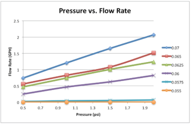
In the analog restrictor we wanted to optimize the range of slot widths that would produce desirable flow rates. We used the caliper and clamped it at different widths between the open tube and a clamping of 0.08 to 0.05 inches. Here are the results of the testing Constricting Flow using Caliper. We then created a prototype with markings at each 0.005 inch spacing and tested these values. Here are the results of the first analog restrictor prototype Analog Restrictor. We found that a valuable range was between 0.075 and 0.06 inches and used this for our final design.
Graph of pressure and flow rate for different widths.Graph of amount clamped and flow rates at different pressures.
FINAL DRIPPER DESIGN
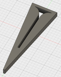
For the final dripper design, we choose to improve on the analog regulator system by running a series of tests to determine the range of widths that captured the useful drip rates at the expected pressures. This range, 0.06 – 0.075 inches, was then used to design a curvature that could easily produce drip rate of around 0.5 GPH at pressures of 0.5 to 2 PSI. With a little practice, drip rates can be approximated by eye since drop sizes remain constant and only rates change.
We also reshaped the plastic around the dripper to be a triangle that can be poked into the ground to keep the dripper in place. This new design uses 30% less plastic than the previous one. Two drippers facing in opposite directions form a rectangle, making manufacturing simpler. Practical testing showed that regulating the flow rate with these drippers at pressures around 0.5-2 PSI was easy and intuitive.
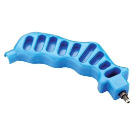
From practical experience, we realized the the cheap ($2-4 in America) hole punchers currently available to prepare pipes for standard commercial drippers make holes that are perfect for inserting 5/32” outer diameter vinyl tubing.
This whole puncher costs $2.25 per unit (in bulk) in America and worked great with our drippers and piping.
CONCLUSIONS
For both large irrigation systems and small gardening kits designed for Western markets, drippers are generally a small fraction of the total system cost when compared to rigid tanks and pressurising pumps. Therefore, few drippers are designed with affordability as the key goal. We believe that our dripper design captures a lot of the advantages of the more expensive professional drippers currently available to farmers in countries like America at a cost that helps make drip irrigation accessible to small-scale farmers in Ghana. The simplicity of the design also makes it easier to use and maintain, though some initial investment of time is needed to set up each dripper.
There are multiple aspects of the design that need to be further investigated before manufacturing could potentially begin. Particularly, we need a better understanding of how prolonged squeezing affects the vinyl tubing. Also, we need to look learn more about the different types of polyethylene tubing to determine which are the best options in terms of price, durability and environmental safety.
We will manufacture and test a row of these drippers by laser cutting next week as we conclude our first design iteration with a focus on filters and drippers before moving on to storage, piping and filling.
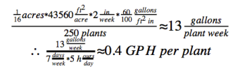
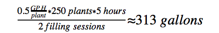
The anecdotal numbers about drip irrigation we have suggest that tomatoes need about 0.5 GPH per plant for 5 hours per day when grown in warm, dry climates. This is just a preliminary number based on the dripper types most commonly suggested for watering tomatoes in California. Some testing will be required to figure out actual water demands in Ghana, but as can be seen below this number does corre-spond well with the commonly cited idea that “Like most other vegetables in the garden, tomatoes need at least one inch of rain or irrigation water per week for steady growth. In the hotter, drier parts of the country, their needs go up to two inches of water per week during the summer months” (source) and with the number of 1.5 inches per week that we got from Nathan.
At this point, it seems good plant health can be achieved with drip rates between 0.4 and 0.6 GPH. Our testing of drippers suggests that this can be achieved with quite low pressures. We have been working on an extremely simple and cheap dripper design specifically for this flow rate that can achieve this rate across a range of pressures and will drastically reduce the cost of producing a drip kit. More on this, as well as technical documentation on our tests, will follow soon.
While we have been mostly focused on drippers and filtration so far, this is also a positive sign for pumping and storage. If the aim of our system is to water a 1/16 acres plot per unit with 250 plants needing 0.5 GPH for 5 hours per day and farmers filling the tank twice daily, then we need a tank volume of around 300 gallons.
This is just slightly higher than the volume contained by the $23 collapsible tank sold by Proximity Designs in Myanmar. In the next iteration of our design process, we are planning to look into the potential of designing a similar tank, better suited for the environmental conditions in Ghana.
Furthermore, with the Kickstart Max treadle pump running 16 gallons per minute, that’s less than 20 minutes of pumping per session. Even with the significantly cheaper Kickstart Hip pump, it’s just 30 minutes. A gasoline powered pump would be able to fill the tank in minutes. This opens up to a wealth of possibilities for filling, including the introduction of a cheaper pump to Burro’s line of products, multiple small-scale farmers sharing the same pump, farmers borrowing pumps for neighbors, etc. These points are just preliminary and will be addressed in greater detail after our second iteration.